
English | Japanese
Overview
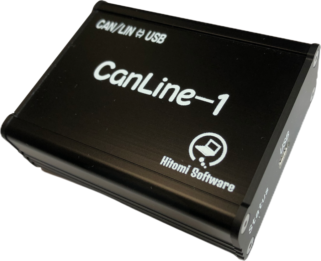
CanLine-1 is a compact, affordable communication tool that connects automotive CAN/LIN networks to a PC or tablet via USB for monitoring and logging with the included software.
Define signals to monitor values in physical units, display graphs, and log data.
The transmission functions also let you edit frame data using physical values to create and adjust frames for node simulation.
A .NET library (DLL) is also available for developing your own applications in VB (Visual Basic) or C#.
Specifications
| Dimensions | 77 × 60.6 × 25.6 mm (W × D × H) |
| Weight | 116g |
| Power Supply | USB bus power |
| Connectors | Target: 9-pin male D-sub PC: Mini-USB |
| USB | USB2.0 |
| CAN | Channels: 2 |
| Transceiver: SN65HVD232D [Texas Instruments] | |
| Termination: 120 Ω (software-controlled ON/OFF) | |
| Protocols: CAN 2.0A and CAN 2.0B | |
| Bit rates (bps): 125k, 250k, 500k, 1000k | |
| LIN | Channels: 1 |
| Transceiver: SN65HVDA100 [Texas Instruments] | |
| Pull-up resistor: 1 kΩ (software-controlled ON/OFF) | |
| Protocols: LIN 1.3 and LIN 2.1 | |
| Bit rates (bps): 2400, 4800, 9600, 19200 | |
| Supported OS | Windows10/11 |
D-sub Pin Assignment
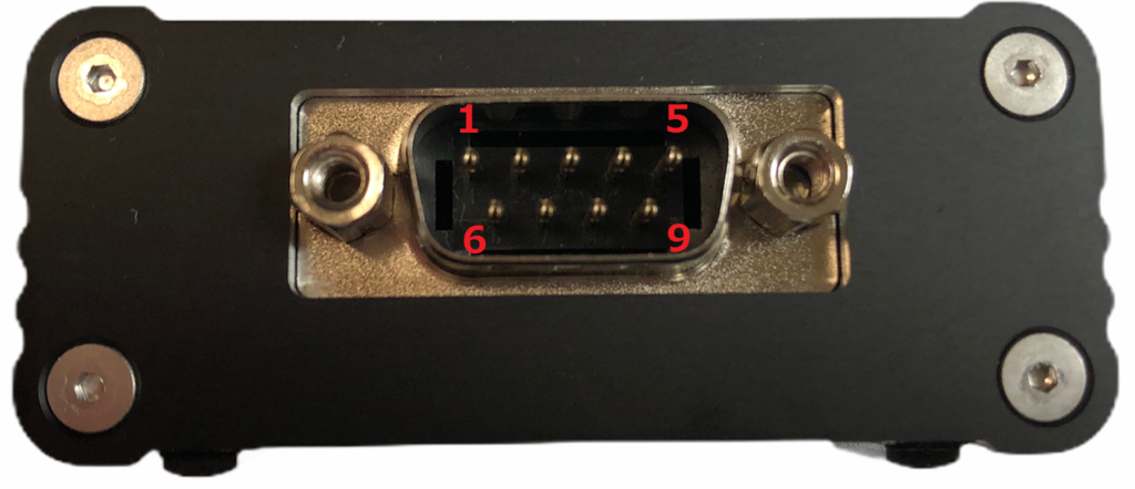
| 1 | CAN2-L |
| 2 | CAN1-L |
| 3 | GND |
| 4 | LIN |
| 5 | NC |
| 6 | GND |
| 7 | CAN1-H |
| 8 | CAN2-H |
| 9 | VB+ |
Key Features
CAN Monitoring
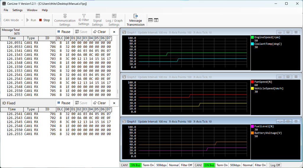
The message window on the left has two panes.
The upper pane displays messages in chronological order; the lower pane shows the latest message for each ID.
On the right, you can display up to three signal graphs in physical units at the same time.
CAN Simulation
[Frames]
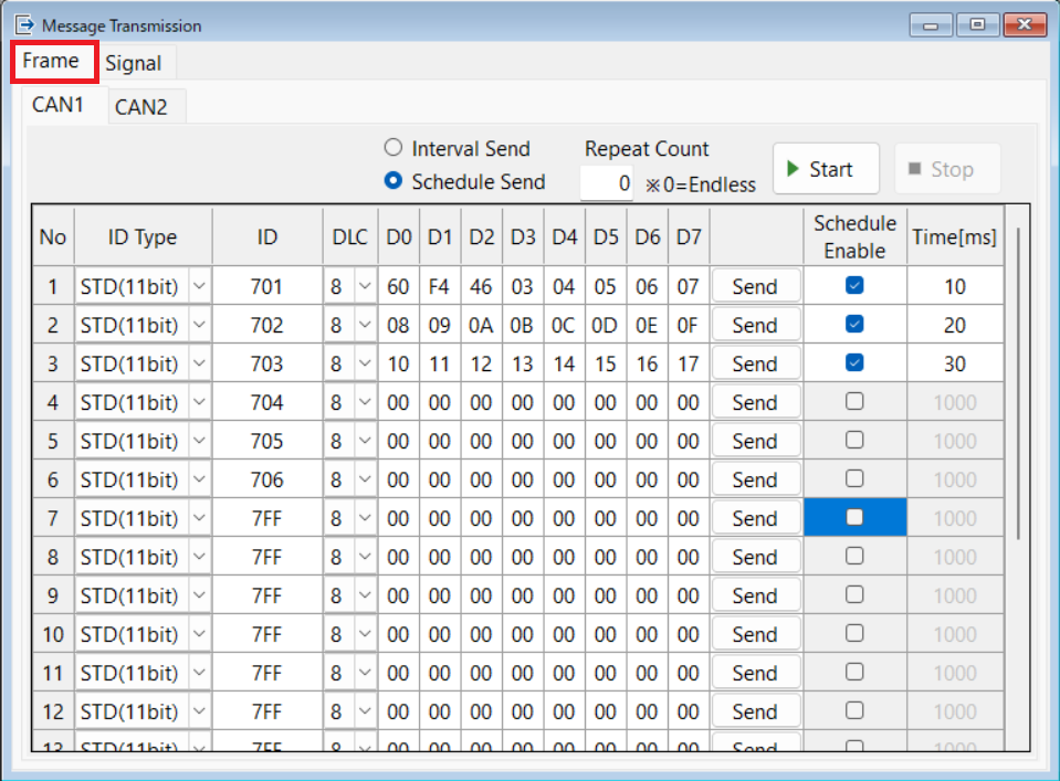
There are 20 transmit boxes. Click [Send] on a row to send its frame once at any time.
Select Interval Send and click [Start] for periodic transmission at a specified interval.
Select Schedule Send and click [Start] for scheduled transmission at specified times.
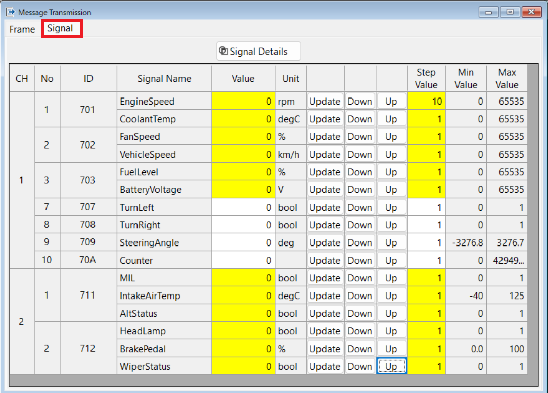
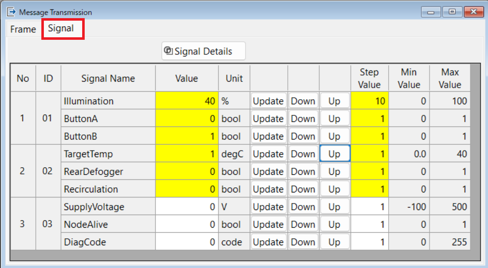
[Signals]
Using the configured signal definitions, you can change frame data in physical units during periodic or scheduled transmission.
Enter a value in [Value] and click [Update], or set the increment in [Step Value] and adjust it with [Up] / [Down].
LIN Monitoring
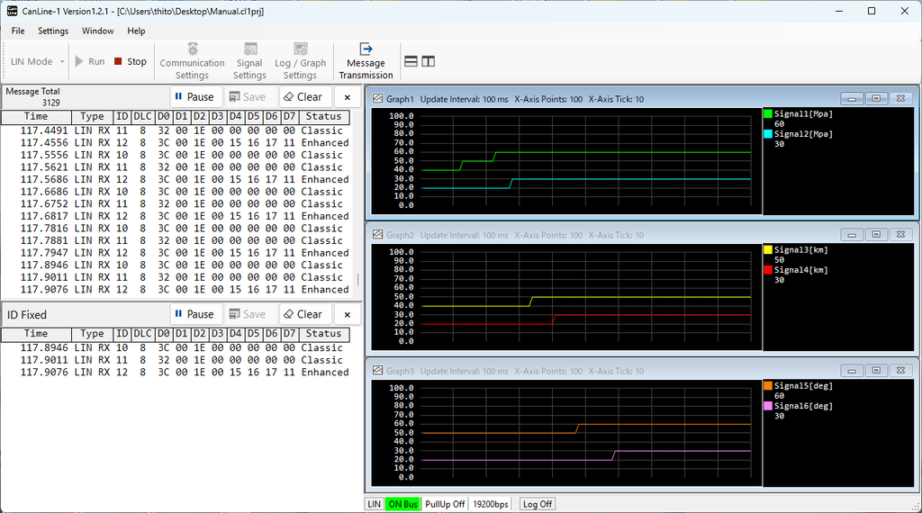
The message window on the left has two panes.
The upper pane displays messages in chronological order; the lower pane shows the latest message for each ID.
On the right, you can display up to three signal graphs in physical units at the same time.
LIN Simulation
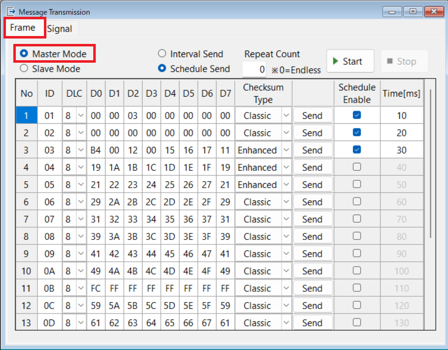
[Frames: Master Mode]
There are 20 transmit boxes. Click [Send] on a row to send once at any time.
Set DLC (data length) to 0 to send only the ID and receive response data from the corresponding slave.
Select Interval Send and click [Start] for periodic transmission at a specified interval.
Select Schedule Send and click [Start] for scheduled transmission at specified times.
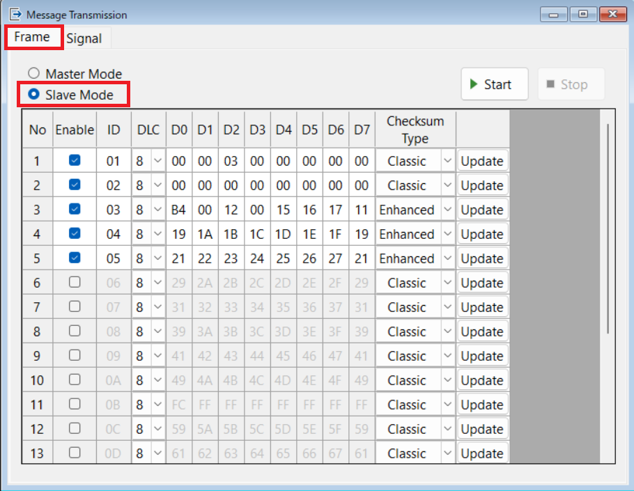
[Frames: Slave Mode]
In slave mode, you can send response data for IDs received from the master.
The 20 transmit boxes allow you to respond to up to 20 different IDs.
[Signals]
Using the configured signal definitions, you can change frame data in physical units during periodic or scheduled transmission in master mode, or while slave mode is running.
Enter a value in [Value] and click [Update], or set the increment in [Step Value] and adjust it with [Up] / [Down].
Price
JPY 55,000 (tax included)
What’s Included
・CanLine-1 unit
・USB cable
・Monitoring and simulation software
Contact
For more information, please use our contact form.